WideBand products can be used with UTP-5 (Category 5) cables. Included here are instructions for making regular cables, which are used to connect workstations or servers to switches, and crossed cables, which are used to connect one workstation directly to another or to connect a server directly to a workstation.
To make a cable for use with WideBand products, you will need Category 5 cable cut to the appropriate length for the workstation involved (up to 300 feet in length; there is no minimum length requirement), two RJ-45 connectors, a crimper tool and a wire stripper.
Begin by stripping back 3/4 inch of cable to expose the multi-colored wires within. There are four color-coded pairs of wires, each pair including one solid-colored wire and one two-colored wire (white plus the corresponding color). Each wire has been assigned to attach to a specific pin in the RJ-45 connector, as shown in Table 1.
| Table 1 – TIA568A Cable Standard | |||||
| Cable Pair | Color | Pin Numbers | |||
| + | – | ||||
| Cable Pair One | Blue (+) | Blue/White (-) | 4 | 5 | |
| Cable Pair Two | Orange (+) | Orange/White (-) | 6 | 3 | |
| Cable Pair Three | Green (+) | Green/White (-) | 2 | 1 | |
| Cable Pair Four | Brown (+) | Brown/White (-) | 8 | 7 | |
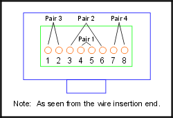
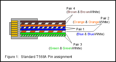
Notice that solid-colored wires always attach to even-numbered pins, while two-colored wires always attach to odd-numbered pins. To work properly, the wires must be arranged in the correct order, as illustrated in Figures 1 and 2.
 Place the wires, one by one, in the order shown in the diagram below, making a flat row in your fingers. Leaving about 1/2 inch of colored wire exposed beyond the end of the cable housing, cut off the excess colored wires. Make sure the cut is straight across the row of wires, so that when they are inserted into the connector, all the ends will reach the end of the connector at the same time.
Carefully insert the wires into the open end of the connector. As you push them in, each one should fit into the channel provided for it. Make sure the wires are pushed completely to the end of the connector. When they are all the way in, you will be able to see the metal end from outside the connector and the outer cable housing will extend part way into the connector.

Place the connector in the crimper tool and gently but firmly squeeze the connector to crimp it onto the wire. (Some crimper tools will not release the wire until it is sufficiently crimped. Whether you are using such a tool or not, however, be careful not to overcrimp, which will cause the cable to fail.)
Follow the same procedure for the other end of the cable. Remember that the finished cable ends should look identical when placed side by side — the green/white wire should be attached to pin one on both ends. The cable may now be tested with an ohm meter or cable tester. If it works, you now have a working Category 5 network cable! If it doesn’t work, cut one of the connectors off the wire and start again.
Crossed Cable
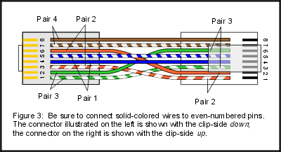
Occasionally you will need a “crossed cable.” To make a crossed cable, make one end of the cable exactly as described above. At the other end, however, reverse the position of cable pair two (pins 3 and 6) with cable pair three (pins 1 and 2). One important detail is that the solid-colored wires must still attach to even-numbered pins. In other words, the solid green wire must be reversed with the solid orange wire and be attached to pin number 6, and the green/white wire, originally attached to pin number 1, is reversed with the orange/white wire, and now attached to pin number 3. (See Figure 3.)


This is an excellent reference for cable re-termination projects. Thank you.